Guide with all the steps necessary for you to change the ZTE Meo Tablet 2 vibrator yourself.


Especificaciones
Dimensiones: 202 x 122 x 12.6 mm
Peso: 389 g
Batería: Li-Ion 3400 mAh battery
Before you start, make sure the tablet is off.


Remove the cap with antennas from the top.


Remove the SIM and SD cards.


Remove the 2 Phillips screws.
Note that the screw on the right is hidden by the adhesive seal.


Separate the back cover, unhooking it from the frame with the double opening tool.


Remove the stickers that cover the flex connectors on the motherboard.


Unplug the flexes from the motherboard, activating the tabs on the connectors.


Take off and set aside the flex.


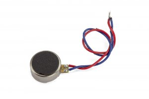
Peel off the components (vibrator, speakers and microphone).


Remove the 2 Phillips screws to separate the flex.


Finally, remove the vibrator from the plate. For this, apply heat with the soldering iron while simultaneously pulling the cable gently.