Guide with all the necessary steps so that you can change the components of the Samsung Galaxy A71 (SM-A71F) yourself.


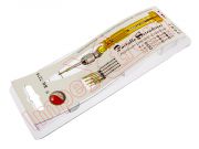
To start we apply heat to the back cover with a thermal mat for 5-7 minutes at 80 degrees Celsius, to soften the adhesive, and, with the help of a fine opening tool, we open a small hole to insert the plastic spike and thus Peel off the edges of the housing without damaging it.


We remove the fourteen Phillips screws (PH # 00), extract the card tray with a SIM extraction tool and carefully unhook the frame with a pick.


We disconnect the battery to work more safely.


We remove the Phillips screw (PH # 00) that holds the motherboard to the screen, disconnect the interconnection flex and the coaxial cable and pry and remove the motherboard.


We can remove the front camera to work with greater comfort, for this we disconnect it with a fine plastic tool and remove it.


With the help of a fine plastic tool we disconnect and detach the macro camera from the front of the motherboard.


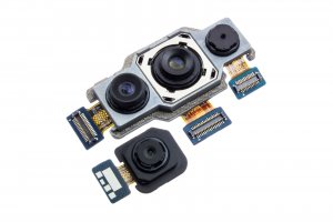
Finally, we disconnect the three cameras (depth camera, main camera, and ultra-wide-angle camera) from the back of the motherboard, apply some pressure, and remove the camera module.