Guide with all the necessary steps so that you can change the components of the Samsung Galaxy A21s (SM-A217 / DSN) yourself.


First we apply heat to the back cover and with a pick we take off the case around its entire contour.


With a fine plastic tool we disconnect the flex from the fingerprint reader to be able to separate the housing from the terminal.


With a Phillips-type screwdriver (PH # 00) we extract the sixteen screws that hold the intermediate casing and extract the sim tray to access the interior of the terminal.


With a fine plastic tool we are extracting the intermediate casing all around its contour until it is separated from the terminal.


With a fine tool we disconnect the battery to avoid any unforeseen event.


With a plastic tool we disconnect the interconnection flex so that the extraction of the battery does not hinder us.


With a fine tool we disconnect the coaxial cable to be able to lift the motherboard


With a Phillips type screwdriver (PH # 00) we extract the fixing screw of the motherboard to be able to remove it from its housing.


With a fine tool we lift the base plate from the side until it is removed from its housing.


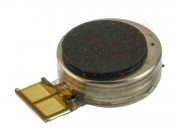
With a plastic tool we lift the vibrator until it is detached from its base and we can extract it.