Guide with all the necessary steps for you to change the Primux Omega X (PTOMX) motherboard yourself.


Primux Omega X
Dimensions: 71.4 x 1415 x 7.8 mm
Before starting, make sure that the mobile is turned off.


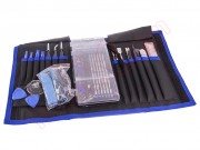
Remove the tray from the cards with an extraction tool.


The back cover is glued with glue all around.
It can be easily removed with a pick. Inserting it under the lid and going around the contour.


Remove the 12 Phillips PH00 screws.
Separate the intermediate housing by prying it gently with an opening tool.


Unplug the battery on the motherboard and detach the battery from the chassis with our opening card.


Disconnect the upper end of the coaxial cable.
Disconnect the flex from the screen, by pulling on the tab of the connector and gently pulling the flex.


Remove the adhesive tape that holds the flex of the touch screen.
Disconnect the flex from the motherboard.
Unhook the support with the volume and ignition switches to remove it next to the plate.


Remove the 5 PH00 Phillips screws that hold the motherboard and auxiliary plate.


Peel off the speaker and the vibrator with the spatula.
Peel off the bottom plate and disconnect the interconnection flex.


Take off the flex and separate the motherboard.
Take off the headset to separate it next to the motherboard.


Unsolder the handset on the motherboard. To do this, apply heat to the tin with the tip of the soldering iron while gently pulling the wire.


Disconnect the cameras from the motherboard.


Take off the flex with the push buttons on the plastic support.


Finally, remove the flex from the ignition and volume buttons on the base plate.
To do this, run the tin of the pins with the tip of the soldering iron while holding the flex. If necessary, apply a little tin to the contacts.