Guide with all the steps necessary for you to change the components of the Google Pixel 4 XL (G020P) yourself.


To begin with, we apply heat to the back shell, and with the help of one or more plastic spikes we will detach all the edges of the shell, and we will have to detach the rear flash from the shell.


We remove the three Torx screws (T4) that hold the shield and remove it, and we will disconnect the battery to work with greater security.


We extract the two Torx screws (T4) that hold the shield that covers the connector of the rear flash, and we will disconnect it.


We extract the 6 Torx screws (T4) that we point out in the photographs, and remove the shields that they hold.


We disconnect the flex from the front camera module, extract the two Torx screws (T4) that hold the module, and with the help of a flat tool we will remove the module.


We take off and remove the battery.


We remove the four Torx screws (T4) that hold the shield that covers the connectors.


We disconnect all the components that are connected on the motherboard.


We disconnect the coaxial cables, extract the card tray, remove the Torx screw (T4) that holds the motherboard, and with the help of a flat tool we will lift the motherboard.


We extract the three Torx screws (T4) that hold the speaker, and with a flat tool we will lift it.


We disconnect the lower microphone connector, remove the Torx screw (T4) that holds it and with the help of tweezers we will take it off.


We disconnect and take off the vibrator.


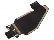
We disconnect the antenna, and with the help of a flat tool we will take off the flex with the charging connector that we have to replace.