Guide with all the necessary steps so that you can change the components of the Apple iPhone Xs (A2097) yourself.


We extract the two Pentalobe screws (TS1) apply a little heat with a hot air gun, and with the help of suction cups we will separate the screen from the chassis with the help of a pick as well.


Remove the shield that is on top of the connectors, for this we must remove the three screws Triwing (Y0.6) and the Phillips screw (PH # 00) that holds the shield, and we can disconnect the flex from the screen and the headset module.


We disconnect all the flexes that are connected on the motherboard.


We remove the tray.


Remove the two Phillips screws (PH # 00) that hold the motherboard to the chassis, but before removing it, we must remove a small shield that is on the top of the plate and that hides two other connectors.


We extract the Phillips screw (PH # 00) and the Triwing (Y0.6) and we can remove the armor that is on top of the cameras and cameras as well.


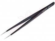
Take off the flex with antenna contacts with the help of flat clamps and remove the two Triwing screws (Y0.6).


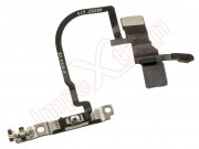
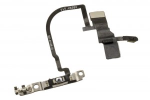
Remove the two Phillips screws (PH # 00), remove the shield that holds the button, and we can take off the rest of the flex.