Guide with all the steps necessary for you to change the back cover of the iPhone 6 yourself.


Before starting make sure that the iPhone is off.


Remove the 2 3.6mm Pentalobe screws, located on either side of the charging connector.


Use the tool with suction cups to easily separate the front panel (screen + accessories) without damaging the equipment.


The front panel will be attached to the base plate by the data flexes at the top. These flex cables are fragile and can be cut or broken, handle them with care.


Remove the Phillips screws that hold the shield covering the connections on the motherboard:


Remove the shield to access the connectors.


Disconnect the flexes from the front panel on the motherboard.


Separate the front panel.


Remove the metal shield covering the battery connector, held by 2 Phillips screws:


Disconnect the battery from the motherboard.


Unplug the flex from the charging module on the motherboard.
Disconnect the coaxial antenna cable.


Remove the SIM card, next to the tray.


Remove the upper cable holder, held by 2 Phillips screws:


Disconnect the flex from the side keys, using the flat part of the opening tool.


Remove the bracket with contacts at the top, held by 4 Phillips screws:


Remove the small metal grounding bracket, secured by 2 x 1.6mm Phillips screws.


Remove the small angled support held by 2 Phillips screws:


Remove the 1.2mm Phillips screw that holds the small antenna interconnect cable.


Disconnect the camera from the motherboard.


Remove the screws that hold the motherboard:


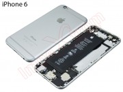
Separate the base plate.


Peel off the battery using a plastic spatula or follow the step:
!!!!!


Retire los 3 tornillos Phillips:


Separate the metal support on which the push buttons of the flex are fixed.
Remove the buttons you need to replace.


Peel off the flex from the shell, pulling gently on it.


Remove the 2 Phillips screws that hold the metal support of the camera:
Remove the small antenna contact on the right side of the camera.


Separate the rear camera.


Remove the metal flash holder, held by a 1.2mm Phillips screw.


Remove the 2 2.2 mm Phillips screws that hold the power button holder.


Remove the power key if you need to replace it.


Take off the flash and the front microphone with the help of a flat tool.


Peel off the flex next to the components, pulling gently.


Remove the 4 Phillips screws that hold the speaker module:
Remove the speaker.


Remove the vibrator, held by 2 Phillips 1.6 mm screws.


Remove the metal support held by 2 Phillips screws of 3.1 mm.


Remove the microphone stand, held by a 3.6mm Phillips screw.


Remove the 6 screws that hold the headphone jack and the charging jack:


Peel off the flex from the housing by pulling gently and using the flat part of the opening tool.
Apply a little heat to the housing on the opposite side to soften the glue and peel off easily.


Peel off the microphone and the headphone jack.
Finally, remove the charging module with headphones and microphone connector.