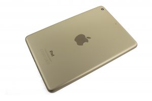
Guide with all the steps necessary for you to change the back cover of the Apple iPad mini 3 (A1599) yourself.


Before starting, make sure the iPad is turned off.


To access the interior of the iPad, we must take off the screen. It has a strip of double-sided adhesive on the entire frame. We will apply heat to soften the adhesive and peel off easily.
We recommend the Hot Glass, a blanket filled with a gel of high thermal retention, suitable for microwaves.
Simply insert the Hot Glass in the microwave for a couple of minutes (see instructions) and apply heat directly to the screen.


You can also use the hot air nozzle of a soldering station to heat the screen.


Hold the screen with the suction cup.
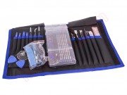
Insert the tip of the prong under the glass and go around the contour to detach the adhesive.
Place thicker tines in the wedge-shaped areas.


Continue until you go all the way around, avoiding the lower side, where the Home button is located. It could damage the flex of the fingerprint reader.


Separate the glass, starting from the upper part and leaving the lower part together. This one carries the delicate data flex.


Remove the remaining adhesive, as well as the small pads that cover the screws in the 4 corners of the display.
Remove the 4 Phillips screws that hold the display.


Go over the contour of the display with the prong to avoid getting stuck with traces of adhesive.
We must turn the display, as we did with the touch screen, leaving the lower part together.


Remove the metal shield, held by 7 Phillips screws.


Remove the metal shield covering the connectors, held by 4 Phillips screws.


Disconnect the data flex from the display on the motherboard.


Unplug the data flexes on the motherboard and separate the touch screen.


Remove the 4 or 3 Phillips screws, depending on the antenna to be replaced.


Remove the adhesives that cover the coaxial cables from the antennas.


Disconnect the coaxial cables on the motherboard.
Release the wires from the metal clip that holds them.


Peel off the speaker antenna to remove it.


Peel off the other antenna and remove it.


Disconnect the battery from the motherboard.
To detach easily, apply heat with the Hot Glass to the back.


Take off the battery with the help of a plastic spatula.


Remove the 3 screws marked in the photograph and remove the metal shields from the connectors.


Unplug and detach the rear camera.


Disconnect the flex from the front camera.


Remove the plastic support.
Take off the front camera.


Unplug and detach the microphone flex. To do this, press the connector tab and pull the cable gently.


Take off the flex with the microphones in the housing.


Unplug and remove the flex with audio connector.


Remove the 2 indicated Phillips screws and remove the power button.


Disconnect and detach the flex from the side keys, exposing the screws.


Remove the flex with the volume, ignition and lock controls.


Do not forget the lock key.


Remove the 2 screws that hold the charging connector.
Push the charging connector to remove it.


Peel off the base plate of the casing.


Finally, remove the 2 speakers.