Guide with all the necessary steps so that you can change the components of the Xiaomi Mi 11 Lite 5G, M2101K9G, M2101K9CG yourself


To begin with, we must apply heat to the back cover in order to soften the adhesive that holds it, and with the help of a plastic tool we will peel off all the edges of the case.


We extract the eleven Phillips screws (PH # 00), which hold the intermediate casing that covers the motherboard area, and with the help of a flat tool we will unhook it.


We disconnect the battery to work with greater safety.


We extract the seven Phillips screws (PH # 00) that are in the lower area, but first we will only remove those that hold the card reader area, remove the tray from inside the reader, disconnect the flex and remove the entire module.


Now we will remove the three Phillips screws (PH # 00) that we did not remove in the previous step, and with a flat tool we will be able to extract the speaker.


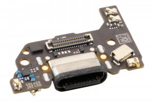
We disconnect the interconnection flex, carefully lift the auxiliary plate, since one of the coaxial cables is connected to the lower area of the auxiliary plate that we are going to replace.


