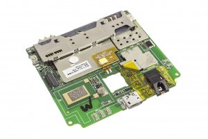
Guide with all the steps necessary to change the motherboard of the Primux Tech Alpha 4 yourself.


Before you start, make sure your mobile is turned off.


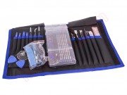
Remove the back cover. Using a plastic opening tool will prevent scratches.


Remove the battery by pulling on the bottom.


Remove the SIM and SD cards.


Remove the 11 Phillips screws that hold the middle housing.


Disassemble the intermediate housing with the opening tool.


The volume and ignition keys are not attached, so that when separating the intermediate casing, they will simply come off.


Remove the adhesive covering the connectors on the motherboard.


Remove the microphone and the vibrator from the intermediate housing.


Take off the touch screen data flex.
Press the connector tab and unplug the flex from the motherboard.


Unplug the display data flex on the motherboard, by pulling the connector tab and pulling gently.


Take off the flex pushbuttons of volume and ignition.


Remove the base plate, fastened by 2 Phillips screws.


Use a suitable support to desolder the components of the motherboard.
Remove the Kapton tape that covers the component pins.


Protect the components that are not to be desoldered with kapton tape.
Apply a little flux so they melt easily.


Point the hot air nozzle to the tin of the pins.
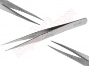
Hold the flex with tweezers and, with great care, pull slowly. The pins will gradually desolder.


We repeat the process with the front camera. We add a little flux and aim the air jet at the flex pins.


Also de-solder the light and proximity sensor, as well as the flex pushbuttons of volume and ignition.


Finally, we desoldered the microphone and vibrator. To do this apply heat with the tip of the soldering iron to the tin while gently pulling the cable.