Guide with all the necessary steps for you to change the components of the Apple iPhone 11 (A2221) yourself.


To begin, we must remove the two Pentalobe 0.8 (TS1) screws from the bottom of the housing, apply some heat to soften the adhesive, and with the help of a tool with suction cups we will take off the chassis screen.


We disconnect the battery connector to work with greater safety.


We remove the five Triwing screws (Y0.6) that hold the shield, and once removed we can disconnect the flex from the screen and the headset module.


We remove the card tray.


We remove the five Phillips screws (PH # 00) that hold the shield and we can remove it.


We take off the rubber that is above the screws.


We remove the three Phillips screws (PH # 00) and the female flat screw that hold the speaker, and with the help of a flat-tip tool we remove it.


Remove the two Phillips screws (PH # 00), disconnect the connector and we can remove the vibrator.


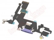
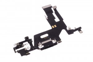
We remove the flat female screws from the bottom that hold the flex with charging connector.


We disconnect the flex connector with charging connector, remove the two Phillips screws (PH # 00) and the female flat screw that hold the card reader and disconnect the connector from the motherboard, and remove it.


We disconnect all the components that are connected to the motherboard, remove the two flat female screws that hold the shield, and disconnect the connectors that covered the shield, and now we can remove the motherboard.


Finally we will remove the two Phillips screws (PH # 00) that hold the charging connector, and with the help of a flat tool we will take off the flex that we are going to replace.