Guide with all the steps necessary for you to change the components of the Nintendo Switch yourself.


To begin with we must remove the four Triwing screws (Y0.6) from the back, and the six Phillips screws (PH # 00) from the sides.


We disconnect the flex from the card reader, and remove the Phillips screws (PH # 00) that hold it.


We extract the six Phillips screws (PH # 00) that hold the shield.


We disconnected the battery to avoid possible damage.


Remove the three Phillips screws (PH # 00) that hold the heatsink support, remove the adhesive that holds it on top, and with the help of a flat tool we will lift it.


We take off and disconnect the internal memory of the motherboard.


We disconnect the flex from the digitizer and the plate with the cartridges reader from the motherboard, extract the three Phillips screws (PH # 00), and once removed we can unhook the cartridge reader module and audio connector.


We disconnect all the components that are connected to the motherboard.


Remove the six Phillips screws (PH # 00) that hold the base plate and with a flat tool we will lift the base plate.


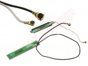
We remove one of the antennas that we are going to replace.


We apply heat to the screen to soften the adhesive and so take it off more easily, helping us with a fine tool to open some gap, and introducing one or more plastic prongs to continue taking off the digitizer without scratching it.


We remove the LCD screen.


We remove the twelve Phillips screws (PH # 00) and remove the side brackets for the controls, and the front frame.


Once the front frame and the lateral supports have been removed, we will be able to extract the last antenna that we have to replace.